 en
en  English
 中文简体
中文简体 Español

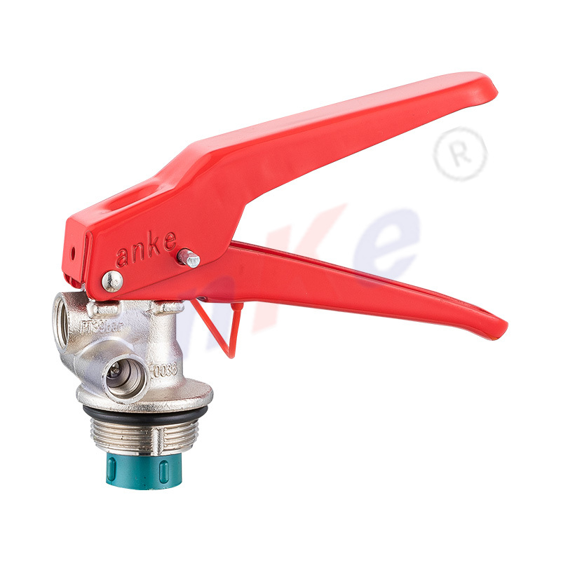
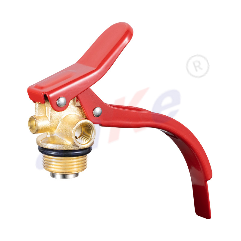
4-12KG Dry Powder Fire Extinguisher Valve 1001
Parameter table
| Material | Copper/Aluminium |
| Surface treatment | According to customer requirements (chrome/nickel plated) |
| Inlet thread | M30X1.5 |
| Outlet thread | M14X1.5/G1/4-19/9/16UNF |
| Gauge thread | M10X1-12.5/NPT1/8 |
| Dip tube pipe thread | M16X1.5 |
| Valve with safety pressure relief device (24±2BAR) | |
-
Description
4-12kg dry powder fire extinguisher special valve, used to release the trigger of the fire extinguishing agent. The valve is made of brass or aluminum, which is resistant to high temperature and corrosion. During the use of the fire extinguisher, the valve plays a vital role to ensure that the fire extinguishing agent can be effectively released to quickly extinguish the fire. Choosing a high-quality valve can not only improve the performance of the fire extinguisher, but also extend its service life and ensure the fire extinguishing effect.
- Machines cleanly to tight tolerances, which matters for thread engagement and seat sealing
- Resists corrosion from dry powder residue and humidity better than plain steel
- Does not generate sparks on impact, relevant given the valve sits on a fire safety device
- Holds up to repeated lever cycling over years of service without the seat surface wearing out of round
- Zinc die-cast valve bodies are lower cost but more prone to cracking under repeated pressure cycling
- Plastic-bodied valves save weight but degrade faster under UV exposure and temperature extremes
- Single NBR-only seals (without a PTFE stem seal) tend to lose elasticity sooner, shortening the interval before a leak develops
- ABC (mono ammonium phosphate) dry powder
- BC (sodium bicarbonate) dry powder
- Purple-K (potassium bicarbonate) dry powder
- Stored-pressure nitrogen propellant systems
- 4kg–12kg steel or aluminum cylinder bodies
- CO2 extinguishers, which need a horn-discharge, siphon-free valve
- Wet chemical (Class F) kitchen suppression systems
- Foam/AFFF stored-pressure units needing foam-compatible seals
- Cartridge-operated heavy industrial cylinders
- Gauge needle sits in the green zone (if a gauge is fitted)
- Safety pin and tamper seal are both intact
- No visible corrosion, dents, or damage to the valve body
- Cylinder is mounted and accessible, not obstructed
- Gauge needle has drifted into the red zone on either side
- Powder is visibly caked or clumped when the cylinder is inverted and shaken gently
- Lever feels loose, sticks, or does not spring back after release
- Cylinder is due for its scheduled hydrostatic retest interval
Anatomy of the Model 1001 Valve
Eight components work together to hold pressure, stay safe in storage, and discharge on demand.
Valve Body
The machined brass housing that threads into the cylinder neck and forms the pressure boundary for every other component.
Squeeze Lever
The hand-operated grip that pushes the valve stem down against spring pressure to open the discharge path.
Safety Pin & Tamper Seal
A removable pin that physically blocks the lever from moving until it is pulled, plus a seal that shows if it has already been removed.
Valve Stem & Spring
The stem seals against its seat when at rest; the spring returns it to the closed position the moment the lever is released.
Siphon Tube
A tube reaching near the cylinder base, sized to the cylinder's height so the discharge draws down close to the full powder charge.
Sealing Rings
NBR O-rings paired with a PTFE stem seal, keeping the nitrogen propellant from slowly leaking past the stem over years of storage.
Pressure Gauge
An optional diaphragm gauge showing whether the cylinder is still within its charged range, without needing to weigh or discharge it.
Rupture Disc
A calibrated weak point that vents pressure automatically if the cylinder is overcharged or heated in a fire, independent of the lever or pin.
How the Valve Works, From Pin to Discharge
The mechanical sequence behind a single squeeze of the lever.
Pull the Safety Pin
Breaking the tamper seal and withdrawing the pin frees the lever to move for the first time.
Squeeze the Lever
The lever presses the valve stem downward, working against the return spring.
The Stem Lifts Off Its Seat
A channel opens between the pressurized chamber and the discharge outlet — the valve is now open.
Stored Nitrogen Drives the Powder
Propellant pressure pushes the dry powder up the siphon tube and through the open stem passage.
Powder Exits Through the Hose or Nozzle
Discharge continues as long as the lever stays depressed; releasing it lets the spring reseat the stem and stop flow immediately, so the extinguisher can be used in short bursts.
Why Brass, and Why These Seal Materials
Material choice on a pressure-bearing safety component is rarely a cosmetic decision.
Brass body (CuZn39Pb3)
Where cheaper alternatives fall short
Model 1001 Against a Typical Market-Grade Valve
The differences that matter to a large-volume buyer usually surface later — in warranty claims or a failed audit, not in a catalog photo.
Testing Coverage
Seal Redundancy
Machining Tolerance
Batch Traceability
Bar lengths illustrate relative emphasis based on internal benchmarking, not a certified numeric score.
What This Valve Handles Well — And What Needs a Different Series
Matching the valve to the agent and cylinder type avoids a mismatched order and a slow return process later.
Handles well
Better suited to a different valve series
Field Seal Replacement, Step by Step
The five-year O-ring replacement noted in the maintenance interval, broken into the sequence a service technician actually follows.
Fully Discharge and Depressurize
Confirm the gauge reads zero before opening the valve body — never service a pressurized cylinder.
Remove the Lever Assembly
Unscrew the retaining nut to expose the valve stem and the seal cavity beneath it.
Extract the Worn O-Ring
Use a nylon pick rather than a metal tool, to avoid scoring the seal groove.
Fit the Replacement Seal Set
Lightly lubricate with a silicone grease rated for dry-chemical agents before seating the new O-ring.
Reassemble and Leak-Test
Torque the retaining nut to specification and confirm the seal with a soap-solution or helium leak test before the cylinder returns to service.
Terminology Reference
Specification sheets from different suppliers do not always use the same vocabulary.
Stored-Pressure Valve
Extinguishing agent and propellant gas share one sealed chamber, ready to discharge as soon as the lever is squeezed.
Working Pressure
Pressure the cylinder is designed to hold during normal storage, measured in bar at 20°C.
Burst Pressure
Pressure at which the cylinder is expected to fail structurally, with a wide safety margin above working pressure.
Neck Ring Thread
Threaded interface between the valve and the cylinder body — the first fit check before assuming compatibility.
Ordering Information for Procurement Teams
The details a purchasing team typically needs before moving a trial order forward.
Sample Orders
Sample sets are available for your own pressure, drop, and corrosion testing ahead of a full order. Sample cost reflects unit price plus shipping, and is credited toward your first bulk order once confirmed.
Minimum Order Quantity
500 units per cylinder size for standard configurations. Custom-engraved or color-anodized variants may carry a separate minimum — confirmed at quotation stage.
Payment Terms
Standard terms are 30% deposit by T/T with the balance due before shipment. L/C at sight is accepted for container-scale orders. Available Incoterms: EXW, FOB Ningbo, and CIF to your destination port.
Warranty
Valves are covered for 12 months against manufacturing defects from the shipment date. Confirmed defective units are replaced on the next order; claims are processed with photos and the batch number from the carton label.
Shipment Documentation
Every shipment includes a packing list, commercial invoice, and a copy of the batch hydrostatic test report. Certificate of origin, CE declaration, and other documents can be added on request at the time of order.
Private Labeling
Carton and pallet labels can carry your company name and item codes at volumes of 2,000 units and above. Artwork requirements are shared once a sample order has been confirmed.
Storage, Inspection & When to Service
What the person responsible for a fire extinguisher on-site — not just the buyer — needs to check.
Monthly visual check
Signs it needs professional servicing
Store extinguishers within the valve's -30°C to +60°C operating range, out of direct sunlight, and upright wherever the mounting bracket allows.
Common Product Questions
What's the difference between the safety pin and the rupture disc?
The safety pin is a manual lock that keeps the lever from being squeezed by accident. The rupture disc is an automatic pressure-relief feature that vents the cylinder if it is overcharged or exposed to fire heat, and works independently of whether the pin has been removed.
Why does the siphon tube length vary between the 4kg and 12kg versions?
The tube needs to reach close to the cylinder base so most of the powder charge can be discharged. A tube sized for a short 4kg cylinder would leave unusable powder at the bottom of a taller 12kg cylinder, so each capacity gets a matched tube length.
Is the pressure gauge mandatory, or can the valve ship without one?
The gauge is optional. Some markets and standards require a visible gauge on stored-pressure extinguishers, while others rely on scheduled weighing instead — the valve body accepts either configuration.
Can the valve be re-machined for a non-standard neck ring thread?
In many cases yes. Sending a drawing or a physical sample of your cylinder's neck ring lets our tooling team confirm whether an existing insert covers it or a new one needs to be cut.
Can we order the valve without the siphon tube or gauge, for our own assembly line?
Yes. Valve body, siphon tube, gauge, and lever can be ordered as separate components, which is common for buyers who fill and assemble cylinders in-house.
Related Products
-
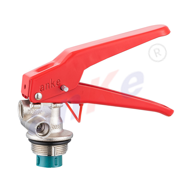
4-12KG Dry Powder Fire Extinguisher Valve 1001
-
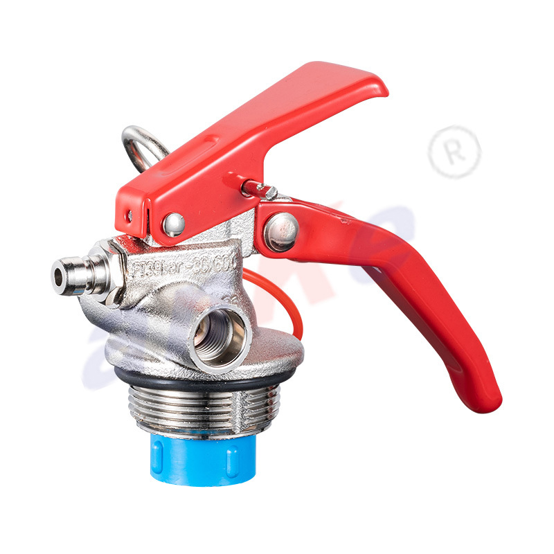
1-2KG Fire Extinguisher Valve 1003
-
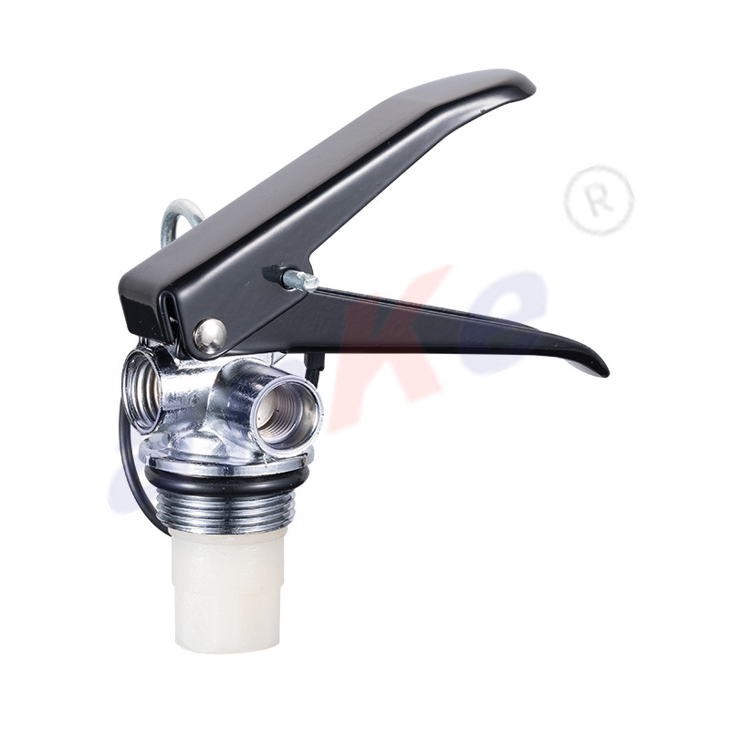
1-2KG Fire Extinguisher Copper Valve 1004
-
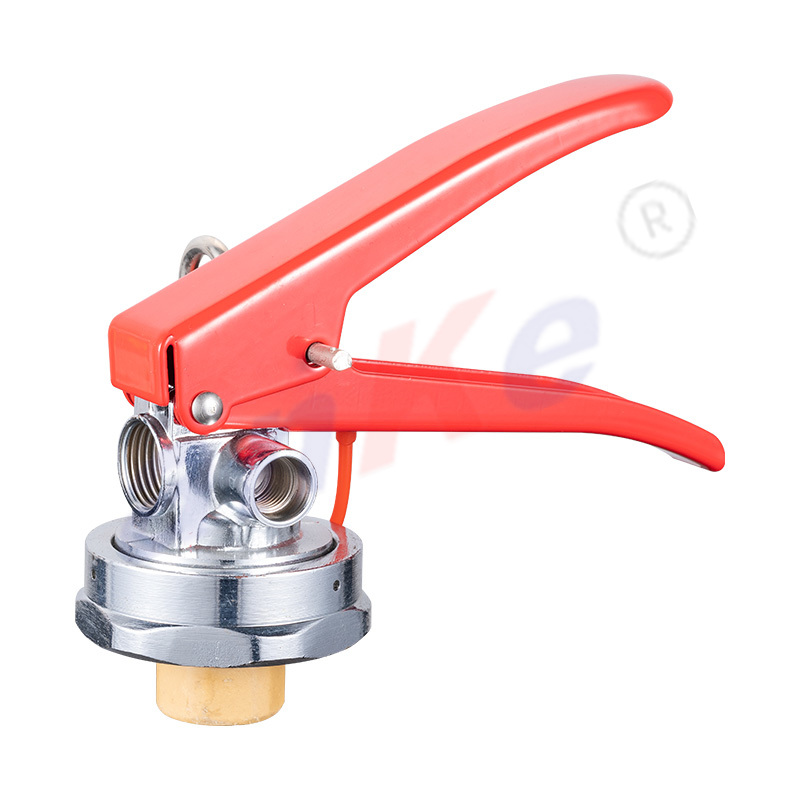
3-12KG Fire Extinguisher High Pressure Valve 1010
-
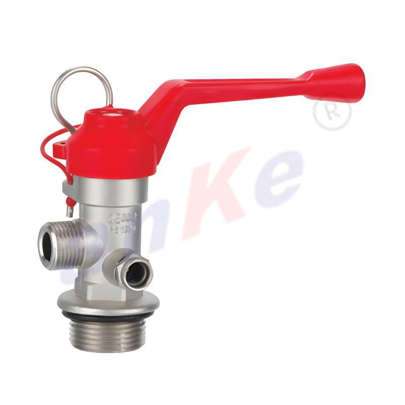
25-50kg trolley type Fire Extinguisher Copper Valve 1036
-
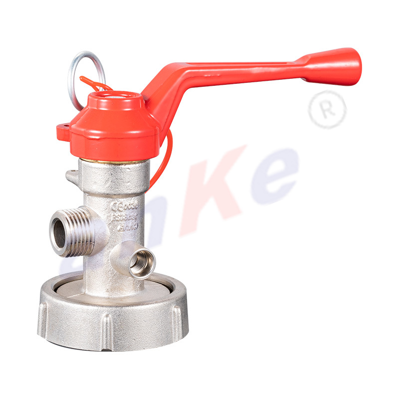
25-50KG fire extinguisher copper alloy valve 1037
-
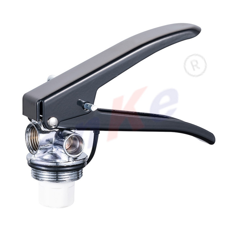
3-9Kg Portable Fire Extinguisher Valve 1017
-
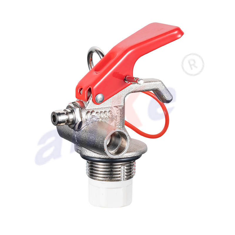
1-2KG Dry Powder Fire Extinguisher Valve 1033
-
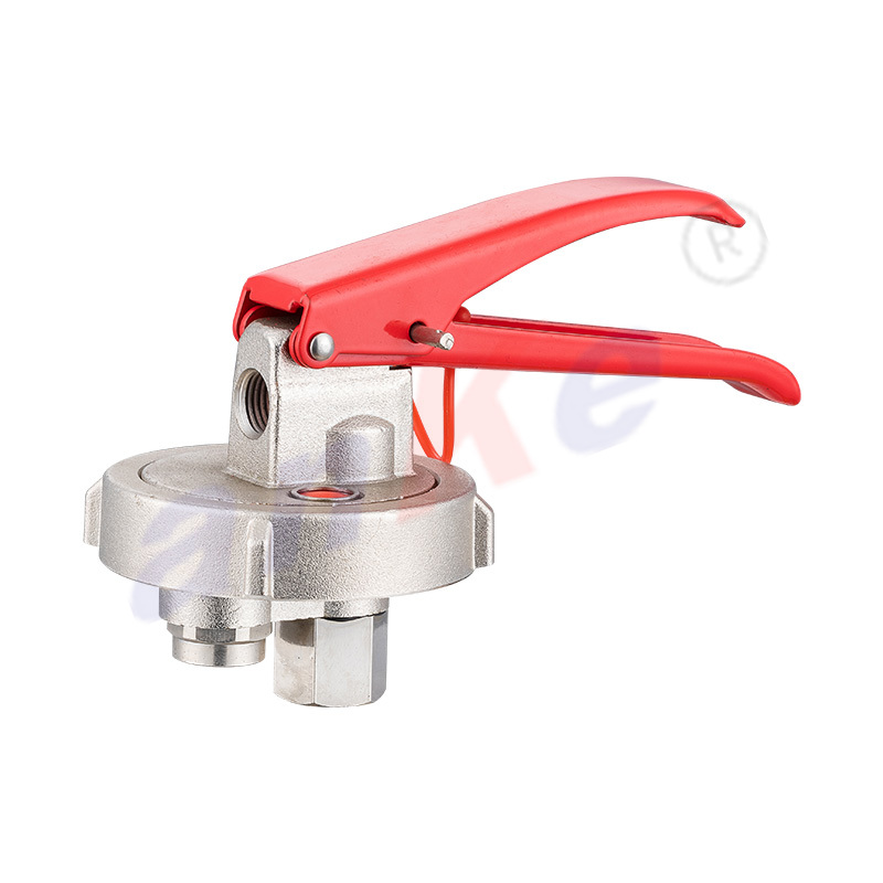
6-12Kg Cartridge Fire Extinguisher Valve 1041
-
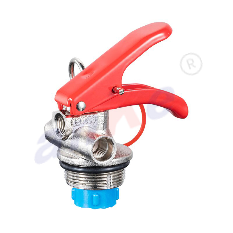
1-2Kg Fire Extinguisher Check Valve 1048
-
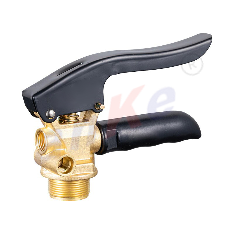
6-12Kg Copper Fire Extinguisher Valve 1065
-
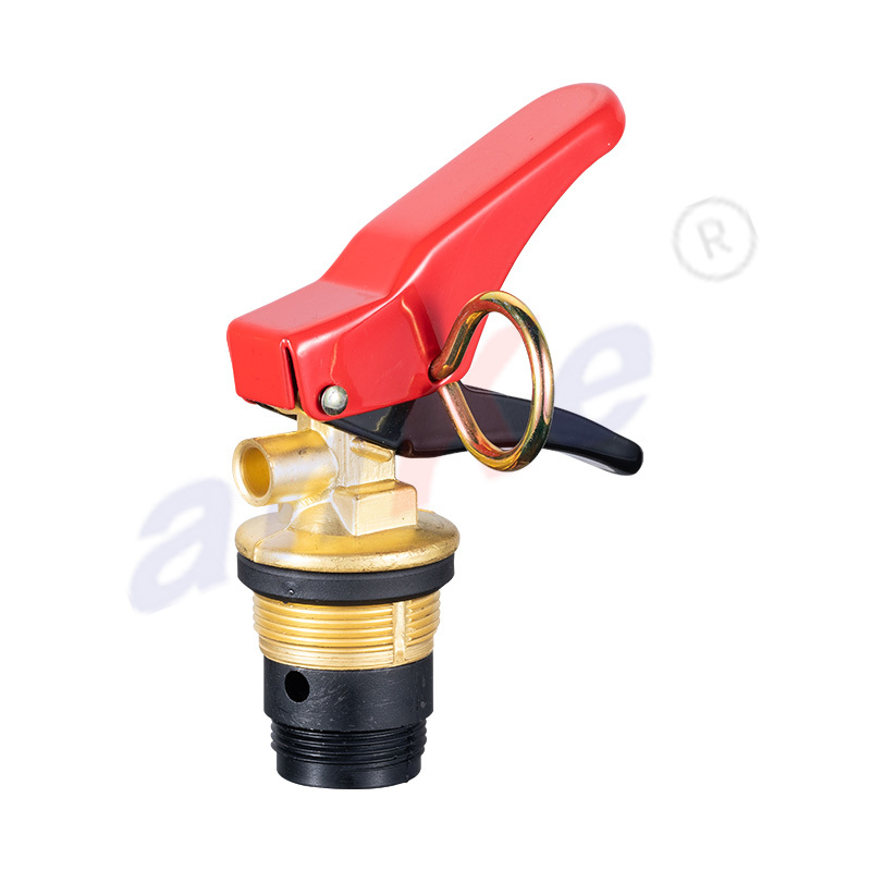
1-2KG Dry Powder Fire Extinguisher Copper Valve 1069A
-
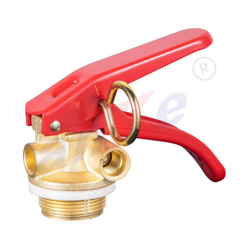
3-12KG Fire Extinguisher Foam Valve 1060
-
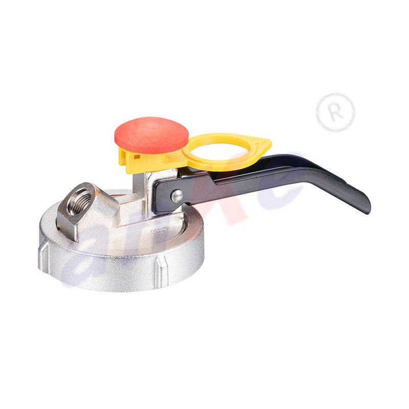
6-12KG Cartridge Dry Powder Fire Extinguisher Valve 1072
-
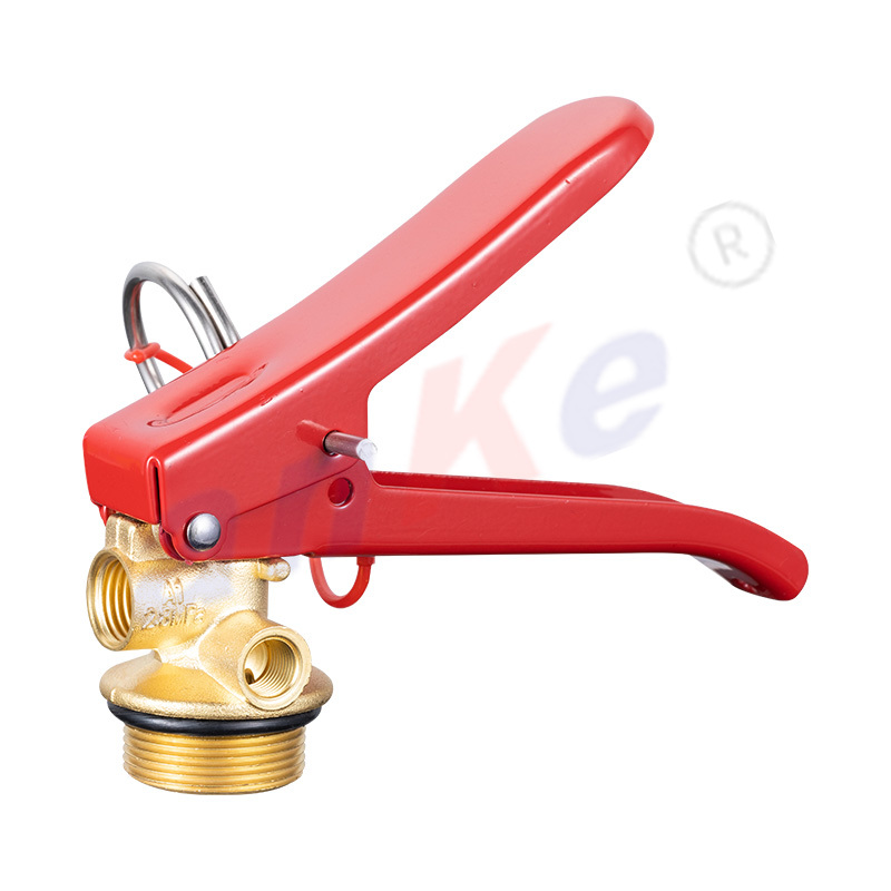
4-12KG Fire Extinguisher Metal Coating Valve 1087C
-
1-2KG Fire Extinguisher Metal-plated Copper Valve 1095
Comfort Starts Here
Founded in 2001, our company mainly provides high-quality fire protection products for the international market, specializing in the production of various types of fire extinguisher accessories, marine gas cylinder valves, gas valves, etc. After years of hard work and continuous improvement of process reform, our products are exported to dozens of countries around the world and have won a good international reputation. All of our products have obtained the EU EN, CE certification in 2007.
Welcome all customers to call and visit us. Our company has a professional sales team to provide accurate services.

 Phone: +86-13456107058/+86-15967800709
 Tel: +86-574-62010128/+86-574-62010688
 E-mail: [email protected]
 Factory: Huilong Village, Huangjiabu Town, YuyaoCity,Zhejiang Province, China
Branch Office: Hengye Building 509, No.158 Tai'an Middle Road, Yinzhou District, Ningbo, Zhejiang, China





 Domestic
 Overseas
 VR Catalogue
Copyright 2024 Ningbo Kaituo Valve Co., Ltd. All Rights Reserved
 OEM/ODM 4-12KG Dry Powder Fire Extinguisher Valve 1001 Factory