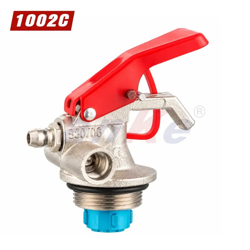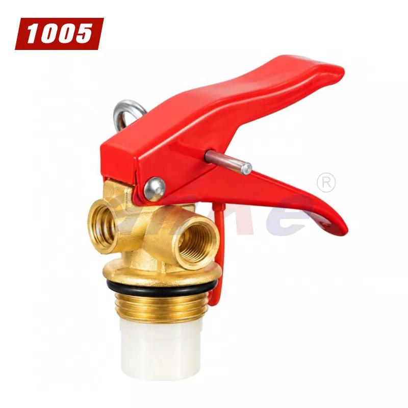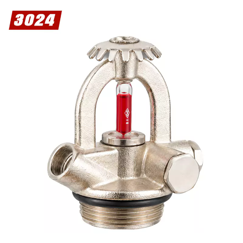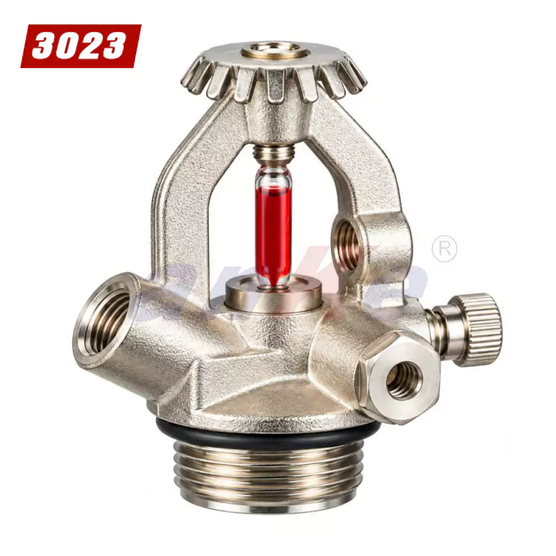
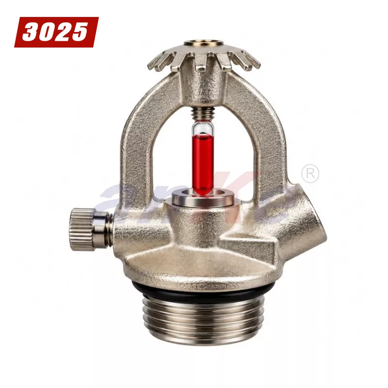
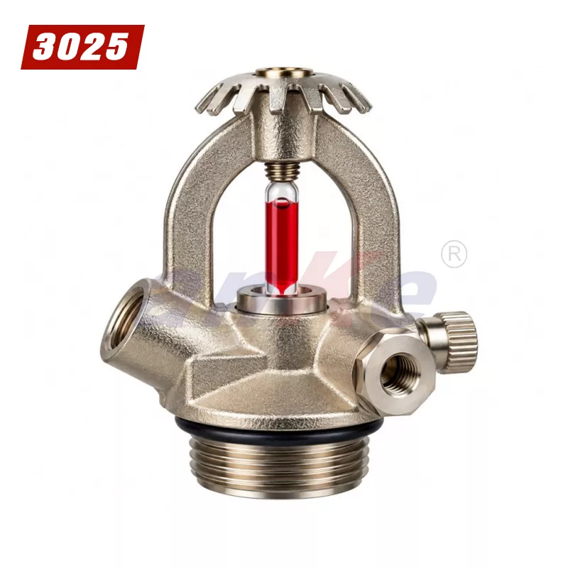
The Metal Sprinkler with Check Valve Model 3025 is a compact metal-bodied component supplied with an M30 × 1.5 inlet thread, an integrated check valve, a dedicated gauge connection, and a documented safety-device pressure range of 22–26 bar. It is intended for evaluation as a component in compatible fire protection or fire suppression assemblies, where the inlet connection, flow direction, pressure-monitoring interface and overpressure function are defined by the equipment design rather than by the sprinkler alone.
The Sprinkler features a metal body designed for mechanical strength and practical integration into compatible equipment. Its compact configuration supports installation where connection dimensions and available mounting space must be considered.
The product features an M30 × 1.5 inlet thread, providing a defined connection interface for compatible assemblies.Accurate thread matching is essential for secure installation and proper sealing.
The sprinkler is specified with an integrated check valve. A check valve is designed to permit flow in the intended direction while helping restrict reverse flow under suitable operating conditions.
The product includes a threaded gauge connection identified in the supplied image as M10 × 1–12.5. This connection may provide an interface for compatible pressure-monitoring equipment, subject to confirmation of the exact thread designation and gauge compatibility.
The specified connection should be verified before installation to avoid thread mismatch, leakage, or damage to connected components.
The supplied specification identifies a safety-device pressure range of 22–26 bar.
| Parameter | Specification |
| Product Name | Sprinkler |
| Model | 3025 |
| Inlet Thread | M30 × 1.5 |
| Gauge Connection Thread | M10 × 1–12.5 |
| Check Valve | Yes |
| Safety Device Pressure Range | 22–26 bar |
| Certifications | CE and TÜV-related certifications |
The 22–26 bar figure describes the pressure band in which the safety device is intended to vent. It is not a continuous working pressure rating for the valve, and the page already notes that this range should not be interpreted as the product’s continuous working pressure without supporting documentation.
The practical question is where that band sits relative to the assembly it protects. In a stored-pressure or wet system, the safety device should open before the pressure reaches a level the downstream components or the equipment design cannot contain. A 22–26 bar band is consistent with assemblies whose normal operating pressure is in the lower part of that window and whose pressure-containing components are rated above the upper end. The suitability of the band should be checked against the maximum allowable working pressure of the specific equipment, rather than accepted as a stand-alone property of the sprinkler. Where the assembly operates at a different pressure regime, the device band and the assembly rating should be reconciled from the equipment documentation.
The integrated check valve is a one-way flow element. In fire sprinkler piping, a check valve retains fluid and pressure downstream of its position during periods such as supply-side system maintenance, so that the downstream section remains charged and isolated from the source being worked on. It also prevents reverse flow through the component under normal operating conditions.
This function is distinct from the safety device. A check valve does not vent overpressure, and it does not replace a pressure-relief function. Where the assembly relies on a relief device, that device performs the overpressure function and the check valve performs the flow-direction and downstream-retention function. Because a check valve can hold pressure in the downstream section, the drain-down arrangement should account for its position; a downstream drain or isolation point is needed if that section is to be emptied for service. The two functions should be verified separately during maintenance, since one can remain operational while the other is obstructed or incorrectly set.
M30 × 1.5 is a metric fine parallel thread. Pressure tightness is not achieved on the thread flanks; the joint depends on a mating seat, gasket or O-ring at the connection. This is a different sealing principle from tapered pipe threads, where the thread interference contributes to the seal. On a parallel thread, the condition of the sealing face and the selection of the correct gasket or O-ring belong to the same assembly check as the thread size.
Published torque values for M30 × 1.5 threaded fasteners and fittings vary widely with material and application, and the higher figures seen in general mechanical tables are intended for steel or cast-iron assemblies rather than for a compact metal sprinkler body. A sprinkler inlet is not a general pipe joint, and the applicable torque should come from the equipment manufacturer’s installation instruction, not from a generic thread chart. Over-tightening a parallel-thread connection can deform the sealing seat or distort the body, while under-tightening can leave the gasket under-compressed. The dimensional drawing should identify the inlet, gauge port and any outlet separately, and the assembly should follow the equipment manufacturer’s sequence.
The gauge connection is identified as M10 × 1–12.5. The notation combines a metric thread designation (M10 × 1) with a figure that appears to reference a shank or body dimension, and the page correctly notes that the exact designation should be confirmed with the manufacturer before ordering. M10 × 1 and M10 × 1.5 share a nominal diameter but have different pitches and do not interchange. A gauge specified for an M10 × 1 port will not correctly engage an M10 × 1.5 port, and a bushing used to adapt between them changes the pressure boundary and should be reviewed as part of the assembly design rather than treated as a field fix.
The gauge side also has its own sealing form. Some gauges seal on a face with a gasket; others rely on a specific thread engagement. The gauge and the port should be matched as a pair, and the gauge should be rated for the pressure range of the assembly, not only for its thread size.
Sprinklers fall within the scope of the Construction Products Regulation, and EN 12259-1 is the harmonised component standard. The attestation of conformity for sprinklers under that standard is System 1, which involves a notified body for initial type testing, initial inspection of factory production control, and continuous surveillance of factory production control. CE marking is therefore not a self-declaration for this product category; the notified body’s number appears in the CE marking information, and a declaration of performance is drawn up against the harmonised standard.
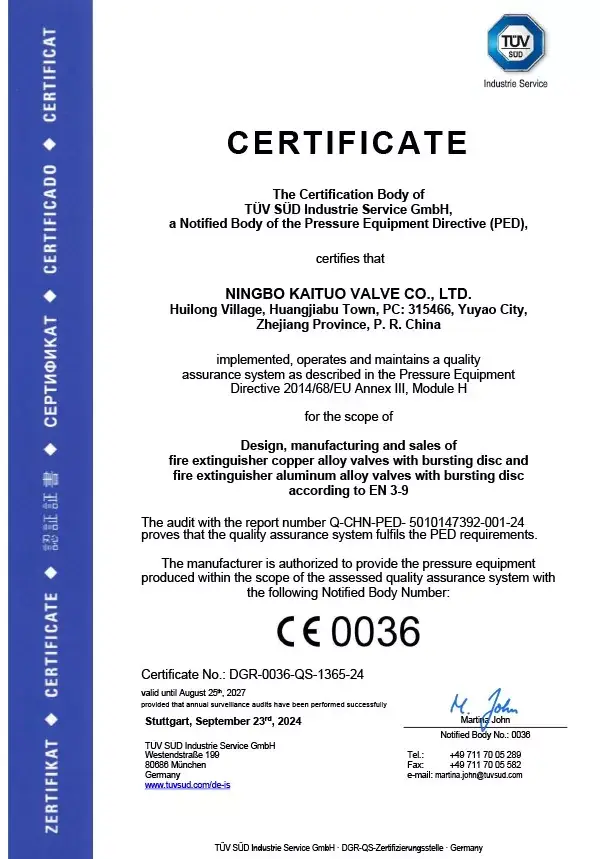
A TÜV document may be a test report, a product certificate, or a factory production control certificate, and the three establish different things. A test report confirms that a sample met specified criteria at the time of testing. A product certificate confirms ongoing conformity of the certified configuration. A factory production control certificate addresses the manufacturing system rather than the product design. For procurement review, the relevant questions are which organisation issued the document, what its scope covers, whether it is tied to the Model 3025 configuration, and whether it remains valid for the production period. A CE declaration of performance and a TÜV test report should be read as separate pieces of evidence, and neither substitutes for the other.
The Sprinkler may be considered for integration into compatible equipment that requires the specified threaded inlet, check-valve function, gauge connection, and pressure-related safety component.
Potential application suitability should be assessed against the verified product design and intended operating environment.
Thread compatibility between the product and the mating component.
Operating pressure and the pressure limits of the complete assembly.
Compatibility with the intended fluid or gas.
Material compatibility and environmental conditions.
Required flow characteristics and installation orientation.
Applicable product standards, certifications, and system-level requirements.
Quality assurance is an important consideration when sourcing components for industrial equipment and fire protection applications.
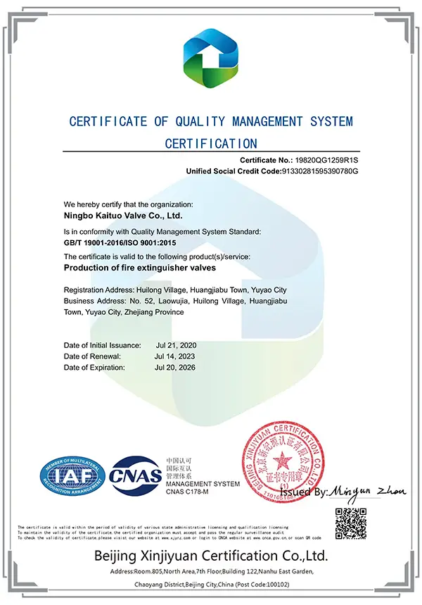
TheSprinkler have CE and TÜV certifications.
Applicable CE Declaration of Conformity.
Relevant TÜV certificate or test report, where issued.
Product-specific technical data sheet and dimensional drawing.
Material specifications and traceability records, where available.
Pressure test or functional test reports, where applicable.
Inspection procedures and quality-control records.
CE marking should be described in accordance with the applicable EU legislation and the product's actual conformity status. TÜV-related claims should identify the issuing organization and applicable certificate or test scope.
Correct installation helps support reliable operation and reduces the risk of connection damage or leakage.
Before installation, verify the inlet and gauge connection specifications, mating-thread compatibility, sealing requirements, and permitted operating conditions. Use suitable fittings and follow the manufacturer's installation instructions.
The check valve and safety device should be inspected and maintained according to the manufacturer's recommendations and the requirements applicable to the complete system.
Any pressure testing, functional testing, or servicing involving safety-critical components should be performed by qualified personnel using appropriate procedures. Do not exceed verified pressure limits, modify the safety device, or use the product outside its approved operating conditions.
The Sprinkler Model 3025 provides a clearly identified inlet thread, an integrated check valve, a designated gauge connection, and a documented safety-device pressure range in a compact metal assembly.
For B2B buyers, these defined characteristics provide a starting point for technical evaluation, component matching, and procurement planning.
To determine whether the Model 3025 meets a specific project requirement, buyers should confirm the complete dimensional drawing, material information, pressure ratings, intended application, and applicable certification documentation.
For distributors, OEM manufacturers, and industrial procurement teams, providing accurate technical records and responsive specification support helps simplify supplier evaluation and reduces the risk of selecting incompatible components.
The specified inlet thread is M30 × 1.5. Buyers should verify the thread standard and dimensional tolerances before installation.
Yes. The supplied product specification identifies an integrated check valve. Its flow direction, operating differential pressure, and performance limits should be confirmed in the manufacturer's technical documentation.
The supplied specification lists a range of 22–26 bar. This figure should not be interpreted as the product's continuous working pressure without supporting technical documentation.
The supplied image identifies the gauge connection thread as M10 × 1–12.5. Because the notation may require clarification, the exact thread designation should be verified with the manufacturer before ordering.
The product is have CE and TÜV certifications. Please request the applicable certificates and supporting documents to verify the issuing organization, product model, applicable standards, and certification scope.
Not necessarily. Suitability depends on the product's intended function, operating medium, connection dimensions, pressure ratings, and applicable system requirements. Confirm compatibility with the manufacturer before use in a fire protection or other safety-critical installation.
Contact our sales team with your required quantity, intended application, destination market, and technical requirements. You may also request the dimensional drawing, complete technical specifications, and applicable certification documents before placing an order.
A8: No. The 22–26 bar band is the pressure at which the safety device is intended to vent, not the continuous working pressure of the valve or the assembly. The continuous working pressure belongs to the equipment design, and the relief band should be checked against the maximum allowable working pressure of that equipment rather than read as a stand-alone rating.
A9: No. A TÜV test report records the results of testing a sample against specified criteria. CE marking for sprinklers under EN 12259-1 involves a notified body under System 1, including initial type testing and factory production control surveillance, and the notified body’s number appears in the CE marking information. A test report is one piece of supporting evidence, not a substitute for the notified body’s role.
A10: No. The check valve controls flow direction and retains downstream pressure; it does not vent overpressure. Where the assembly requires pressure relief, that function must be provided separately and set against the assembly’s pressure limits. The check valve also affects drain-down, because it can hold pressure in the downstream section unless a drain or isolation point is provided.
Address
Factory: Huilong Village, Huangjiabu Town, Yuyao City, Zhejiang Province, China
Branch Office: Hengye Building 509, No.158 Tai'an Middle Road, Yinzhou District, Ningbo, Zhejiang, China
Tel