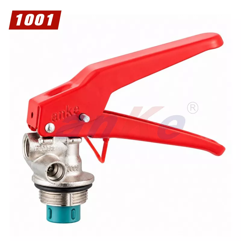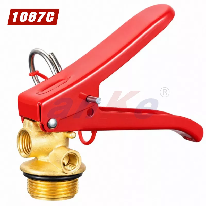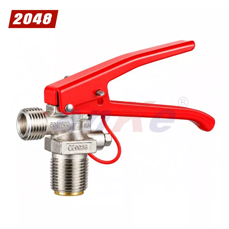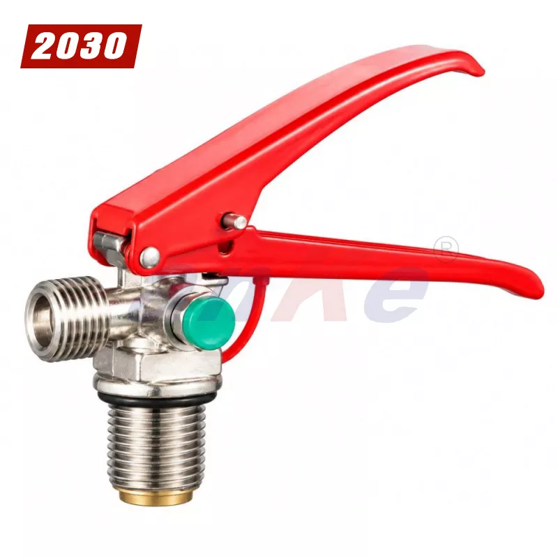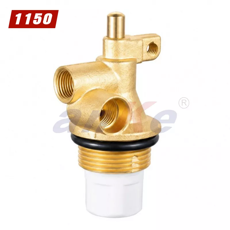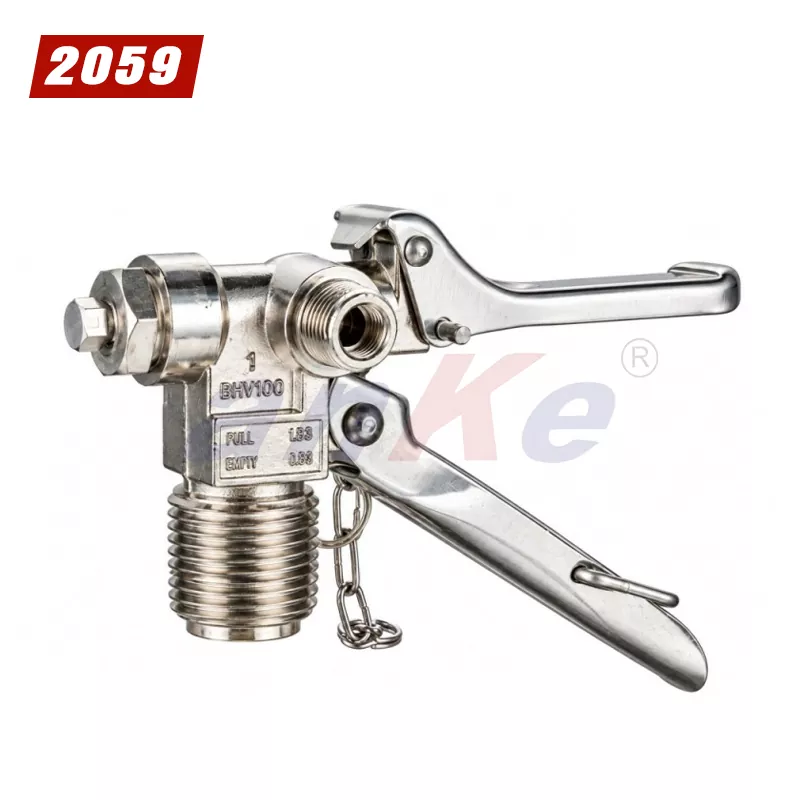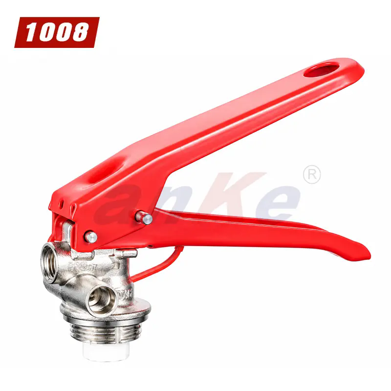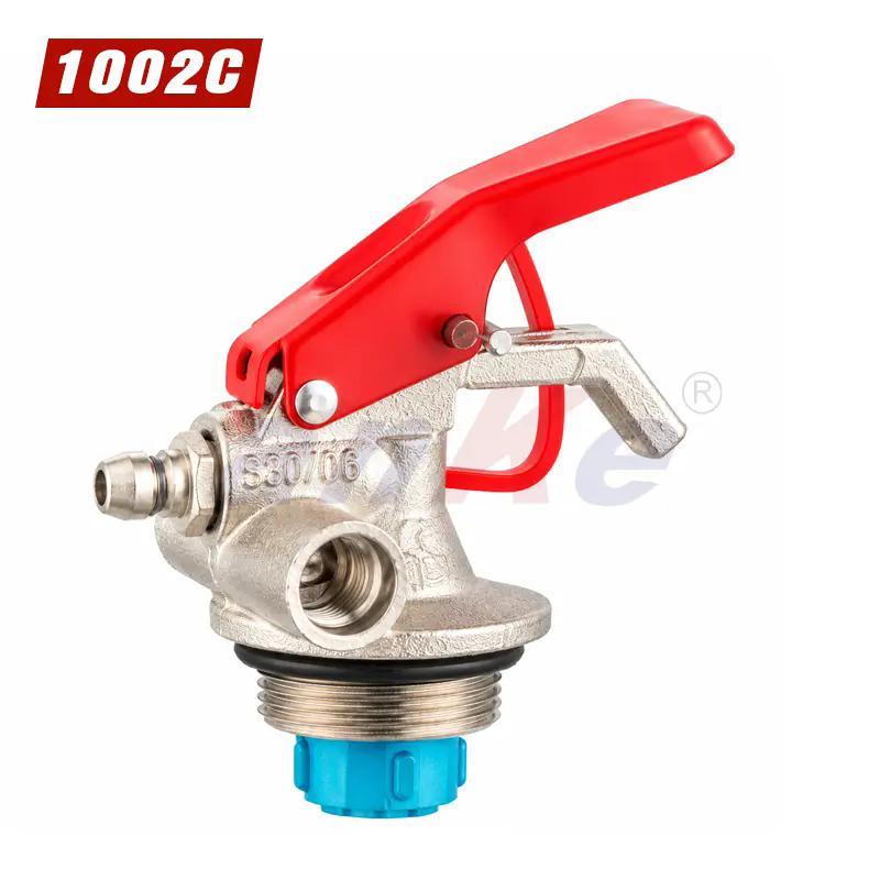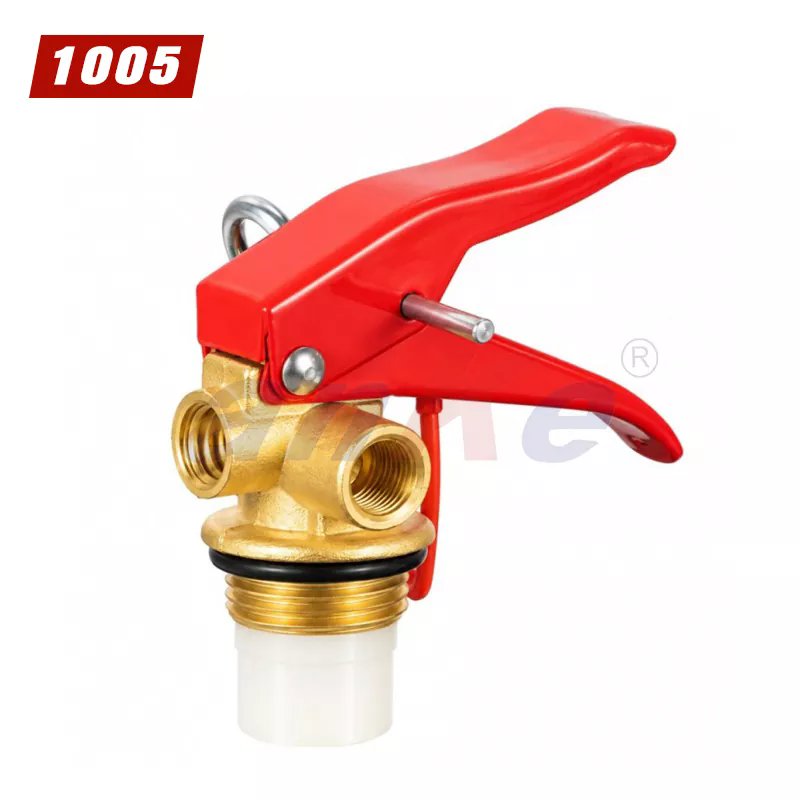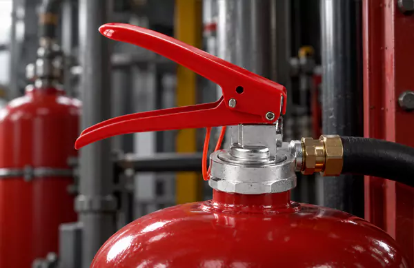
A dry powder fire extinguisher is a pressure vessel with a valve at the top, a hose at the outlet, and a safety mechanism that must work after years of storage. The valve is the component that connects the vessel, the hose, the gauge, and the operating lever. If any of those connections is wrong, the extinguisher may leak, fail to discharge, or fail to hold pressure during a real event. For a manufacturer assembling extinguishers, the valve connection details are not a purchasing formality. They are the dimensional and sealing requirements that determine whether the finished unit passes the pressure test and the discharge test.
This guide is written for procurement and quality teams who source Dry Powder Fire Extinguisher Valves. It identifies the connection details that must be verified before a valve is accepted into production: the cylinder thread, the sealing interface, the hose and nozzle connection, the gauge port, the torque specification, and the batch documentation. Each section explains what to check, why the check matters, and what evidence the valve supplier should provide. The content is organized around the verification sequence that a manufacturer should follow, and it includes the product parameters and test records that a reliable supplier should supply. Our factory at Ningbo Kaituo Valve Co., Ltd. manufactures Dry Powder Fire Extinguisher Valves for extinguisher assembly, and the guidance below reflects the connection checks we perform before shipment.
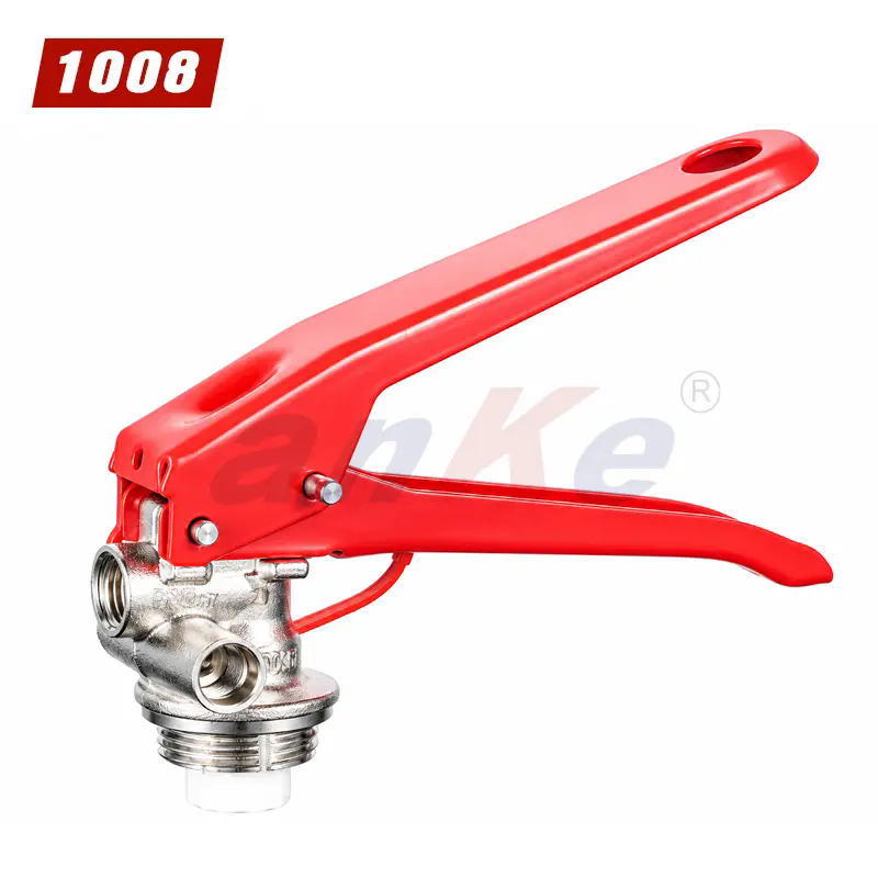
The first connection to verify is the thread that joins the valve to the extinguisher cylinder. This thread is the primary structural and sealing interface, and it must match the cylinder neck exactly. The verification starts with the thread standard. Dry powder extinguisher valves commonly use metric threads such as M30x1.5, M24x1.5, or inch threads such as G1/2, depending on the regional standard and the cylinder design. The thread form, pitch, and tolerance class must be confirmed against the cylinder drawing, not against a generic catalogue value. A valve with the correct nominal diameter but the wrong pitch will start to engage and then bind, and a valve with the wrong tolerance class may feel loose or may not seal even when fully tightened.
The table below lists the connection parameters that should be measured and recorded for every valve batch.
| Parameter | What to Verify | Typical Specification | Verification Method |
| Thread standard | Metric or inch, thread form | M30x1.5, M24x1.5, G1/2, or per cylinder drawing | Thread gauge and drawing comparison |
| Thread pitch | Distance between threads | 1.5 mm, 1.0 mm, or per standard | Pitch gauge and optical measurement |
| Tolerance class | Fit between valve and cylinder | 6g/6H or per drawing | Go/no-go thread gauges |
| Thread length | Engagement depth | Per cylinder neck depth | Depth gauge and assembly trial |
| Thread surface | Burrs, damage, coating | Clean, no burrs, coating per spec | Visual inspection and thread feel |
| Concentricity | Thread axis to valve body axis | Within 0.05 mm TIR | Dial indicator on a mandrel |
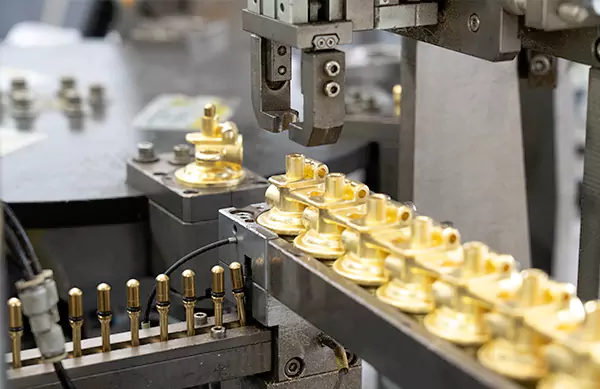
The concentricity check is often overlooked, but it matters for the sealing interface. If the thread axis is not aligned with the valve body axis, the valve will sit at a slight angle on the cylinder. The angle may be small, but it can create uneven compression on the sealing washer and can cause a leak at the cylinder neck. Our factory at Ningbo Kaituo Valve Co., Ltd. checks the thread concentricity on a sample from every batch before the valves are packed, and we retain the measurement records with the batch documentation.
For a manufacturer, the thread verification should be performed at goods-in, not only at the valve supplier’s factory. A thread that is correct at the supplier can be damaged in transit or mixed with another batch at the warehouse. The receiving inspection should include the thread gauge check, the thread length check, and a trial assembly on a sample cylinder. The trial assembly is the most direct check, because it reveals whether the valve engages smoothly and whether it seats against the cylinder neck without a gap. If the trial assembly shows a gap or a tight spot, the batch should be quarantined and the supplier should be contacted before the valves are used in production.
The sealing interface is the surface where the valve contacts the cylinder neck, and it is the connection that determines whether the extinguisher holds pressure over its service life. The seal is usually a washer, an O-ring, or a formed gasket that is compressed between the valve body and the cylinder neck. The leak-tightness depends on three factors: the flatness of the valve seating face, the surface finish of the cylinder neck, and the compression force that the thread develops when the valve is tightened. If the valve seating face is not flat, the washer will not compress evenly, and a leak path will form. If the cylinder neck is rough or damaged, the washer will not seal against it. If the thread does not develop enough compression force, the washer will not be compressed enough to seal.
The failure chain below describes how a small sealing defect becomes a field failure.
The sealing interface should therefore be verified on three levels. The first level is the dimensional check of the valve seating face: flatness, surface roughness, and the absence of burrs. The second level is the washer or O-ring check: material, hardness, thickness, and compression set. The third level is the assembly trial: the valve is tightened onto a sample cylinder, and the assembly is pressure tested. The table below summarizes the sealing interface checks.
| Check | What to Verify | Acceptance Criterion |
| Seating face flatness | No concavity, convexity, or tilt | Within 0.05 mm across the face |
| Surface roughness | Finish of the sealing face | Ra 1.6 µm or better |
| Burr and damage | No burrs, nicks, or scratches | Visual inspection at 3x magnification |
| Washer material | Material and hardness | Per drawing, NBR or EPDM as specified |
| Washer thickness | Compression allowance | Per drawing, within tolerance |
| Assembly leak test | Pressure hold after tightening | No leak at the specified test pressure |
Our factory at Ningbo Kaituo Valve Co., Ltd. inspects the sealing face and the washer on every Dry Powder Fire Extinguisher Valve batch, and we perform the assembly leak test on a sampling basis. The test results are recorded and retained. For a manufacturer, the sealing interface is the connection that most directly affects the pressure hold test. If the valve passes the dimensional check but fails the assembly leak test, the cause is almost always the seating face or the washer, and the batch should be reviewed before assembly continues.
The hose and nozzle connection is the outlet side of the valve, and it determines whether the extinguisher can deliver the powder at the required rate. The connection includes the valve outlet thread, the hose coupling, the hose itself, and the nozzle. The verification should cover the thread match, the hose coupling security, the hose pressure rating, and the nozzle orifice size. The thread match is the first check: the valve outlet thread must match the hose coupling thread, and the coupling must engage fully without cross-threading. The hose coupling security is the second check: the coupling must be crimped or clamped to the hose so that it cannot pull off under pressure. The hose pressure rating is the third check: the hose must be rated for the extinguisher’s working pressure and the test pressure. The nozzle orifice size is the fourth check: the orifice must match the discharge rate specified for the extinguisher class.
The table below lists the hose and nozzle connection parameters that should be verified.
| Parameter | What to Verify | Typical Specification |
| Outlet thread | Thread standard and size | M16x1.5, G1/2, or per drawing |
| Coupling engagement | Full thread engagement, no cross-thread | Hand-tight plus specified turns |
| Hose pressure rating | Working and burst pressure | Above extinguisher test pressure |
| Coupling pull-off | Coupling security on the hose | No movement at specified pull force |
| Nozzle orifice | Diameter and discharge rate | Per extinguisher class and standard |
| Hose flexibility | Bend radius and kink resistance | Per application requirement |
The hose and nozzle connection is often tested as part of the extinguisher discharge test, but the connection details should also be verified at goods-in. A hose coupling that is not fully engaged may pass a static pressure test but separate during discharge, when the flow and the movement of the hose apply additional loads. A nozzle orifice that is too large will reduce the discharge time and may reduce the discharge range. A nozzle orifice that is too small will increase the discharge time and may not deliver enough powder to extinguish the fire. Our factory at Ningbo Kaituo Valve Co., Ltd. supplies Dry Powder Fire Extinguisher Valves with outlet threads and couplings that match the customer’s hose specification, and we provide the thread and coupling data with each batch.
For a manufacturer, the hose and nozzle connection should be verified with a pull test and a flow test. The pull test confirms that the coupling will not separate under the specified load. The flow test confirms that the nozzle orifice produces the required discharge rate. Both tests should be performed on a sample from each batch, and the results should be recorded. If the valve outlet thread is correct but the hose coupling is from a different supplier, the two may not engage correctly. The manufacturer should confirm that the valve outlet thread and the hose coupling thread are from the same standard and the same tolerance class.
The gauge port and the accessory connections are the smaller interfaces on the valve, but they are just as important for the extinguisher’s reliability. The gauge port holds the pressure gauge, and it must seal against the gauge stem without leaking. The accessory connections may include the safety pin, the tamper seal, the carrying handle, and the mounting bracket. Each connection has a different function and a different verification method. The gauge port is a threaded or a push-fit connection, and it must be checked for thread match, seal integrity, and gauge orientation. The safety pin and the tamper seal must be checked for fit and for correct operation. The handle and the bracket must be checked for structural security.
The checklist below covers the gauge port and accessory connections that should be inspected before assembly.
The gauge port is the connection that most often causes a slow leak after assembly. The leak may be small enough to pass the initial pressure test, but it can drain the extinguisher over months. The gauge port seal should therefore be inspected on every valve, and the gauge should be tightened to the specified torque. Our factory at Ningbo Kaituo Valve Co., Ltd. checks the gauge port thread and the seal on every Dry Powder Fire Extinguisher Valve batch, and we supply the gauge port specification with the valve documentation. The goal is to ensure that the gauge connection is as reliable as the main cylinder connection.
For a manufacturer, the accessory connections should be verified during the assembly trial. The gauge should be installed, the safety pin should be inserted, and the handle should be operated. If any of these actions feels tight, loose, or misaligned, the valve should be inspected before the extinguisher is filled. A valve that passes the pressure test but has a binding safety pin is a valve that may fail at the moment of use.
The torque and assembly checks are the final connection details that prevent field failures. The valve must be tightened onto the cylinder to a specified torque. If the torque is too low, the sealing washer will not compress enough, and the extinguisher will leak. If the torque is too high, the valve body or the cylinder neck can be damaged, and the thread can be over-stressed. The hose coupling must also be tightened to a specified torque, and the gauge must be tightened to its own specification. The table below presents the torque and assembly checks that should be included in the assembly procedure.
| Check | Specification | Verification Method |
| Valve-to-cylinder torque | Per valve and cylinder specification | Calibrated torque wrench |
| Hose coupling torque | Per coupling specification | Calibrated torque wrench |
| Gauge torque | Per gauge specification | Calibrated torque wrench |
| Thread engagement | Full engagement, no gap | Visual and feel check |
| Safety pin operation | Free movement, no binding | Manual operation |
| Lever operation | Smooth travel, returns to position | Manual operation |
The torque check should be performed with a calibrated wrench, and the wrench should be calibrated at the interval defined by the quality system. A torque wrench that is out of calibration can produce a joint that is over-tightened or under-tightened, even though the operator believes the torque is correct. The assembly procedure should also include a first-article check, where the first extinguisher of a batch is inspected for thread engagement, torque, and leak-tightness before the rest of the batch is assembled.
Our factory at Ningbo Kaituo Valve Co., Ltd. provides the recommended torque values for our Dry Powder Fire Extinguisher Valves, and we mark the valve body with the torque specification where the design allows. We also provide the thread engagement depth and the assembly sequence in the product manual. For a manufacturer, the torque and assembly checks should be part of the work instruction, not a verbal instruction to the operator. A written instruction with a calibrated torque wrench is the simplest way to prevent a field failure caused by an assembly error.
The batch documentation is the evidence that the connection details have been verified. A manufacturer should not accept a valve shipment without the documentation package, because the connection details cannot be verified from the valves alone. The package should include the material certificates, the dimensional inspection report, the thread gauge report, the leak test report, and the assembly torque record. The table below lists the documents and the connection details they cover.
| Document | Connection Detail Covered | What to Verify |
| Material certificate | Valve body and internal materials | Grade and traceability |
| Dimensional inspection report | Thread dimensions, seating face, outlet | Measured values vs. tolerances |
| Thread gauge report | Cylinder thread and outlet thread | Go/no-go results for each batch |
| Leak test report | Sealing interface and gauge port | Test pressure, duration, result |
| Assembly torque record | Valve, hose, gauge torque | Torque values and wrench calibration |
| Batch traceability record | All connection details | Batch number, date, inspector |
The documentation should be reviewed at goods-in, and any missing or incomplete document should be treated as a nonconformance. A supplier that provides a certificate of conformance without the measured data is a supplier that is asserting the connection details are correct without evidence. A supplier that provides the measured data and the test records is a supplier that is controlling the connection details. Our factory at Ningbo Kaituo Valve Co., Ltd. provides the documentation package with every Dry Powder Fire Extinguisher Valve shipment, and we retain the records for traceability.
For a manufacturer, the batch documentation should be linked to the receiving inspection record. The receiving inspection should confirm that the thread gauge results, the leak test results, and the torque records match the batch number on the carton. If the documents cannot be linked to the batch, the verification is incomplete. The documentation package is therefore not a paperwork exercise. It is the chain of evidence that connects the valve to the extinguisher and the extinguisher to the user.
Question 1: What is the most critical connection detail to verify in a dry powder fire extinguisher valve?
Answer: The cylinder thread and the sealing interface are the most critical details because they determine whether the extinguisher holds pressure. The thread must match the cylinder neck in standard, pitch, and tolerance class, and the sealing face must be flat and free of burrs. A thread mismatch can cause a leak or a damaged cylinder neck, and a sealing face defect can cause a slow leak that passes the initial pressure test but fails in the field.
Question 2: How can I verify the valve-to-cylinder thread before assembly?
Answer: Use a go/no-go thread gauge that matches the cylinder thread standard, and perform a trial assembly on a sample cylinder. The gauge confirms the thread dimensions, and the trial assembly confirms that the valve engages smoothly and seats against the cylinder neck without a gap. Record the results for each batch and quarantine any batch that fails the trial assembly.
Question 3: Why does the gauge port cause slow leaks after assembly?
Answer: The gauge port has a small seal that can be missing, damaged, or made from the wrong material. If the seal is not correct, the extinguisher can lose pressure slowly over weeks or months. The gauge port should be inspected on every valve, the seal should be verified, and the gauge should be tightened to the specified torque. A slow leak at the gauge port is often missed because the pressure loss is gradual.
Question 4: What torque should be used for the valve-to-cylinder connection?
Answer: The torque should be taken from the valve and cylinder specification, not from a generic table. The correct torque depends on the thread size, the sealing washer material, and the cylinder neck material. Use a calibrated torque wrench and record the value. Over-tightening can damage the valve or the cylinder neck, and under-tightening can leave the sealing washer uncompressed.
Question 5: What documents should accompany a valve batch to verify connection details?
Answer: The batch should include material certificates, the dimensional inspection report, the thread gauge report, the leak test report, the assembly torque record, and the batch traceability record. These documents connect the measured connection details to the specific batch. A certificate of conformance without measured data is not sufficient evidence that the connection details have been verified.
The connection details in a Dry Powder Fire Extinguisher Valve are the cylinder thread, the sealing interface, the hose and nozzle connection, the gauge port, the accessory connections, and the torque values. Each detail must be verified with the correct gauge, the correct test, and the correct documentation. A valve that passes a visual inspection but fails a thread gauge or a leak test is a valve that will cause a field failure. For manufacturers, the verification should be performed at goods-in and during assembly, and the batch documentation should be reviewed before the valves are released to production. Our factory at Ningbo Kaituo Valve Co., Ltd. manufactures Dry Powder Fire Extinguisher Valves with the connection dimensions, sealing performance, and documentation that manufacturers need to verify. If you are sourcing valves for extinguisher assembly, contact our team to discuss the cylinder thread and the connection specifications for your production line.
Contact Ningbo Kaituo Valve Co., Ltd. today to discuss your Dry Powder Fire Extinguisher Valves requirements and to request the connection specifications and batch documentation for your production line.
-